2021年1月28日星期四

INVT GD3000 Series Drive Applied to Oil Drilling Rig

Abstract: This paper has introduced the feature of oil drilling rig, INVT GD3000 series 3-level frequency drive, and the application on drillings rig in Russia.

Keywords: Oil & gas, drilling rig, frequency drive, 3-level, GD3000

1.Forewords

Oil drilling rigs are massive structures housing equipment used to drill oil wells, or natural gas extraction wells, which are capable of drilling through thousands of meters of the Earth's crust.

An oil drilling rig is mainly composed of three main transmission mechanisms, Rotary table, winch, and mud pump.

Rotary table: rotates the drill string along with the attached tools and bit.

Draw-works: to raise/lower the pipe, drill string and drill bit.

Mud pump: to circulate drilling mud (slurry) through the drill bit and up the casing annulus, for cooling and removing the "cuttings" while a well is drilled.

These mechanisms are driven by common DC bus inverters. Usually an oil drilling rig operates 24h every day, it requires the inverters have the extremely high reliable performance.


Fig.1 Simple illustration of drilling rig[2]

2.Project introduction

The project is located in Samara, Russia, there are totally 11 sets of drilling rigs.

The electrical control part is mainly composed of a series of containers called "e-house", including VFD (Variable Frequency Drive), MCC (Motor Control Center), HVR high-voltage room and driller's room.

One VFD room adopts 7 sets of common DC bus GD3000 inverters to drive the winch motors, mud pump motors and rotary table motor.


System one-line diagram:


Fig.2 System one-line diagram


3.Advantage


Fig.3 GD3000 3-level inverter diagram

1)Output waveform is better than 2-level inverter, more similar to sine wave


2)Low dU/dt, low peak voltage to motor, reduce damage to motor insulation
3)Lower harmonic under same carrier frequency, THDi<5%, THDu <3%
4)High overload capacity (150% 1min, 180% 10sec), and big torque at low frequency
5)Standard field bus Profibus-DP and ProfiNet, compatible with the mainstream controller
6)Multiple protection functions, ensure system reliability
7)Modular design, easy maintenance


4.Site photos


Fig.6 Field site photos


5.Conclusion

Oil drilling rig is the highest level of application in the oil industry. Rig equipment generally faces complex and harsh external working environment, and has a high rigid demand for advanced equipment and reliability. With excellent product performance, reliable product quality and good market reputation, INVT products have been successfully applied in the core equipment of oil drilling rigs, breaking through the long-term monopoly of international first-tier brands.


Reference

[1]Shenzhen Invt Electric Co., Ltd. < Goodrive3000 Series Inverter Operation Manual >
[2]www.passmyexams.co.uk . < Drilling for Crude Oil - The Drilling Rig>

2020年12月16日星期三

Application of GD20-EU and IVC Series PLC on Roller Coaster

INTRODUCTION

A set of carts looking like a small dragon rides on an oval track with alternating ascents and descents. It serves for the joy of children and their adult parents on the occasion of various festivities or in amusement parks.


Pic. 1 Little Green Dragon


DESCRIPTION

Before the start of the attraction, the roller coaster stays on the parking sensor.

The parking sensor serves for several purposes:
-parking the set
-ride laps counter
-measurement sensor of actual roller coaster speed for correction of drives frequency (lower losses and less stress on the wheel mechanism)

After the start, the roller coaster accelerates synchronously to maximum speed by both vfd drives. Then the roller coaster is running around with inertia itself for whole ride lap.

After the roller coaster leaves the station, frequency of the drives decreases to previous calculated speed level (actual speed of the roller coaster).

Maximum frequency is applied by reaching of the speed sensor located in front of the first drive (wheel) mechanism. It accelerates the roller coaster to maximum speed.

After elapsing of set number laps following things happen:
-timing out after passing speed sensor causes the roller coaster deceleration to zero speed
-parking in reverse direction at a slow speed onto the parking sensor
-a new ride can begin after that

There are several modes with different numbers of wheels. If the roller coaster is outside the parking sensor for some reason, parking sequence can be started as following:
-slow move forward direction
-timing
-slow move reverse direction
-stopping onto parking sensor


Pic. 2 The principle of operation


CONTROL

The roller coaster is controlled by INVT PLC IVC1L 2416 MAR and drive control with two GD20- 011G-4-EU drives. External braking resistors are also installed.

Drives are working as MASTER - SLAVE interconnection via analog signals.

The first drive (MASTER) takes frequency reference from PLC via MODBUS serial communication.

The second drive (SLAVE) one takes frequency reference from analog output of MASTER drive, which is monitoring its frequency reference.


Pic. 3 Electrical Cabinet


Reference: Roller coaster Little Green

2020年11月30日星期一

INVT Medium Voltage VFD Applied to Steel Main Fan in Thailand

Summary: In this case,through introducing INVT GD5000 medium voltage drive applied to main fan in steel in the Thailand to illustrate economy and characteristics of variable frequency drive. Especially significant energy saving.

Keyword: GD5000 medium voltage drive, TATA steel, main fan, energy saving.

1.Project introduction and analysis

N.T.S steel group PLC. Co Ltd is one steel manufacturer plant in Thailand. This plant belongs to TATA steel group Thailand. TATA steel group is the 6th largest steel company in the world.

There are three main fans used baffle to control air speed and air flow. This is the old technology speed control method, through this way has below disadvantages:

1) Narrow adjusted speed range.
Due to baffle control method can't be elaboration and sensitive, so the system adjusted speed range is narrow.

2) High maintenance costs for pipe network of air.
There is lots of big and long pipe network of air in the working process. Because of air is high pressure, those pipes need much maintenance work and costs during whole plant maintenance period.

3) High power loss.
Because of baffle control method is old and outmoded speed control technology, there is much power consumption during speed adjust period.


Figure 1.N.T.S. steel group PCL


2. System Configuration

2.1 Motor introduction.

Detailed motor parameters are list as follow:

Table 1.Main fan motor Parameters

Motor ModelPowerRated VoltageRated CurrentRated SpeedPower FactorLoad Type
AMA 450L6ABAM1000KW6600V104A991RPM0.88Main fan


Figure 2.The main fan motor nameplate


2.2 System solution.
Based on INVT experience on steel industry VFD renovation project, INVT can supply whole solution for the customer.

According to customer demand, the variable frequency drive consists of transformer cabinet, power cell cabinet and control cabinet. The GD5000 VFD has function of local/remote button and emergency stop button on control cabinet.

INVT suggest VFD solution:

Table 2.VFDs for main fan

VFD ModelPowerRated VoltageRated CurrentQuantity
GD5000-A1250-6.6-S1000kw6.6KV109A3


Main systme diagram:


Figure 3.The system diagram


Figure 4.The main fans VFD and motor


3. Application and Advantage

After using VFD, there are some major advantages as follow:

1.Wide range speed adjusted.
Because VFD is a step-less speed regulation, the main fans can be run smoothly with wide speed range. It means that the speed adjusted can be elaboration and sensitive.

2.Increase grid line power factor.
The grid line power factor is over 0.97. It can increase efficiency of the grid power.

3.Energy saving.
The main fan and it system running at optimal situation and can save energy. From the site real running situation, the energy saving ratio is about 30% by roughly calculate.

4.Perfect output waveform.
Output waveform is perfect, less than 2% of distortion.

5.Prolong motor working life time.
VFD can keep motor running at optimal situation.

4. Conclusion

Compared with old technology, the VFD driven method has many advantages. Especially significant energy saving. The energy saving ratio can reach 30%. The transformational VFD system works very well, customers are satisfied with INVT solution and INVT VFD met with customer's requirements.


References

[1] GD5000 Series Medium-voltage Variable Frequency Speed Control System Manual.    Shenzhen INVT Electric CO., LTD.

2020年11月11日星期三

INVT GD35-07 Series Tension Control Drive used in Printing Machine

Abstract: The invention of printing machine is a sign of the improvement of human automation technology. It not only liberates human hands, reduces the workload, but also greatly improves the printing quality and efficiency. It is one of the essential automation equipment at present. Taking the printing machine system of a mechanical factory as an example, this paper introduces in detail the system solution of INVT GD35-07 series drive on printing machine.

Keywords: Gooddrive35-07, Printing machine, Open loop tension torque control, Coil diameter calculation

1. Introduction

With the development of power electronic technology, machine tool technology and information technology, the level of human automation technology is gradually improved. The invention and application of printing press is a best example.

Printing process belongs to the flow production operation, and the whole printing process includes two motion chains: press and paper feeding. This requires the printing machinery and equipment to be able to reasonably control the paper feeding motion chain and the printing press motion chain, so as to ensure that the printing materials can move according to the requirements and complete various printing operations in the process of printing materials.

Variable frequency inverter is a popular control device in printing machine in recent years. It uses frequency conversion technology and microelectronics technology to adjust the frequency and voltage of motor power supply. The rapid development of mechatronics technology and the maturity of inverter technology will further promote the application of inverter in printing and processing industry.

2. Control requirements

This paper takes a mechanical factory as an example. The site printing machine system needs to control three motors: two nos 2.2kW asynchronous motors (for main machine and unwinding) and one 1.5KW asynchronous motor (for winding). And the inverter configuration is as below:

Application Motor rating Qty Drive
Main motor 2.2kW 1 GD300-004G-4
Winding 1.5kW 1 GD35-07-004G-4-C1
Unwinding 2.2kW 1 GD35-07-004G-4-C1


The requirements for inverter are as follows:
a) The paper tension should be stable in the whole equipment operation, and the tension can be adjusted by external potentiometer.
b) Three motors are master-slave control speed synchronization; the speed is given by the master.
c) At zero speed, the motor should be stable and not shake.
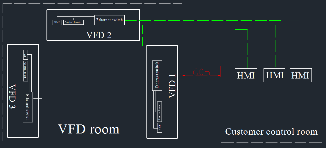
d) The communication performance should be good anti-interference performance.

3. Introduction of Goodrive35-07 inverter

Goodrive35-07 inverters special for tension control focus on the textile industry, printing and packaging industry, plastic machinery industry, paper industry, cable manufacturing industry. It has the function of tension control and coil diameter calculation and meets the requirements of medium and high-end winding applications.

In the algorithm, the tension control module is special for the tension control of winding/unwinding and the comprehensive solutions of the whole processing segments.

Use Goodrive35-07 tension control special inverter can replace torque motor, dc motor, such as tension controller and independently constitute a tension control system, and compared with traditional tension controller and frequency converter control scheme, the use of the frequency converter can make the system more concise, reduce cost, easy to maintain and gain more stable control effect.

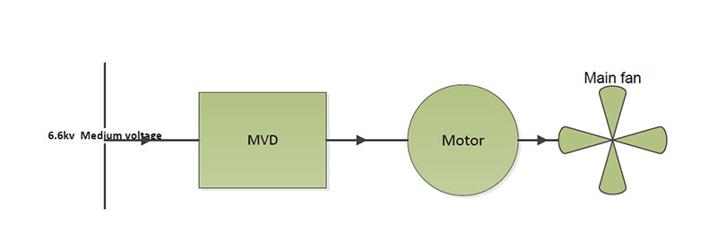
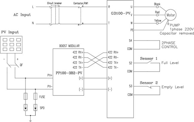
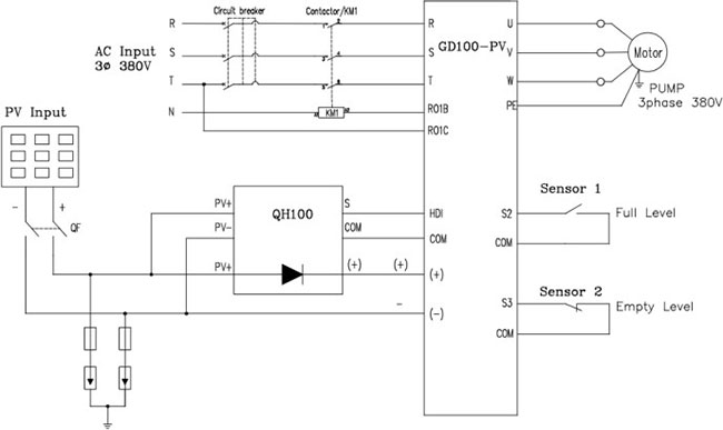
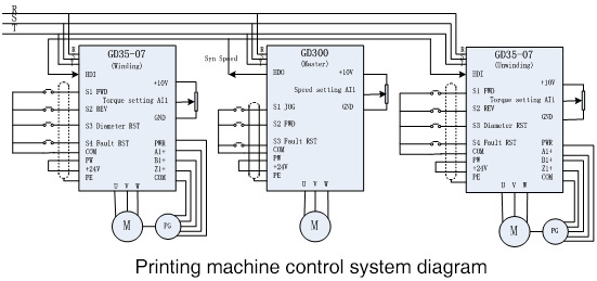
4. System diagram and commissioning


4.1 System commissioning

Step 1: Motor autotuning, it is better to perform rotating autotuning for parameters identification;

(1) Set P00.18=1, restore to the factory setting
(2) Set P00.03 and P00.04 and P02 group
(3) Motor autotuning
a) Set P00.15=1, perform rotating autotuning
b) Set P00.15=2, perform static autotuning

If the motor can be de-coupled from the load, it is necessary to perform rotating autotuning; otherwise perform static autotuning, and the parameters after autotuning are saved in P02 group.

Step 2: Asynchronous motor close loop (encoder fitted on motor)

(1) Check the installation and parameters setting of the encoder
Set P20.01, P00.00=2, P00.10=20Hz and start the inverter. The frequency is 20Hz and observes the tested value of P18.00, if the value is negative, the direction of the encoder is reversed and set P20.02=1. If the tested value is large, the setting of P20.01 is wrong.
Observe P18.02 is fluctuated or not (counting value of Z pulse). If it fluctuates, there is interference to the encoder or the setting of P20.01 is wrong, check the wiring and shield layer.

(2) Close loop vector operation
Set P00.00=3 and begin close loop vector control, adjust P00.10, P03 group and PI parameters to stabilize the operation.

(3) Weakening control
Set P03.26=0~2000 and observe the control performance. P03.22~P03.24 can be adjusted according to the actual situation.

Step 3: Open-loop tension torque control mode

(1) Set basic parameters of production control such as the linear speed, tension reference, gear ratio and diameter of blank coil and cancel out the zero voltage through setting the lower limit of analog input in P05 group;

(2) Set the upper frequency of torque control and max output frequency
Set P26.02=0, P26.03=100.0% and observe the frequency value displayed by P19.05. Take this value as the max output frequency P00.03, upper limit frequency P00.04 and as torque control forward rotation, reverse upper limit frequency value P03.16, P03.17, then modify P26.02 as actual channel source.

(3) Select the counting mode of coil diameter: P26.13=1 (Calculation method of linear speed)

(4) Check the tension and the compensation torque

1) Identify the fixed moment of inertia of mechanical system
When no materials, if set P27.13 = 1, the keypad will display "-GuA-". After press the operation key, the motor will runs and when the keypad display "-End-", the identification is finished. The identified inertia will be saved in P27.15.

2) Set the torque compensation coefficient of mechanical friction
Set p27.13 = 2, the automatic identification of mechanical friction torque will be completed.

3) Set the materials tension and adjust the torque compensation coefficient of mechanical friction
Set P26.00=2 when there are materials on the coil, on the basis of friction compensation coefficient, adjust the materials tension, static friction compensation coefficient, sliding friction compensation coefficient and high speed torque compensation coefficient and so on.

And ensure following parameters when blank coil:
a). Ensure the tension reference after stopping when the linear speed is zero. If the required tension is smaller, then increasing P27.05 which is only valid below P27.06, if it is bigger than P27.06, then it will become to 0 gradually;
b). Adjust the static friction compensation coefficient at some frequency which is below the threshold;
c). Accelerate gradually, make the running frequency is between the threshold value and 1/4 of the upper limit and then adjust the sliding friction compensation coefficient;
d). Adjust the high speed torque compensation coefficient at some frequency which is between 1/2 of the upper limit and the upper limit. After that, the parameter adjusting is finished and then decelerates. Observe the materials, and reduce the sliding friction compensation coefficient and high speed torque compensation coefficient; generally the compensation coefficient is less than or equal to the basic torque which is set through the tension value (observe through P19.19);
e). Set the linear speed to close to the Max. value, start the machine directly and observe whether there are materials loose during ACC and materials pressing during DEC. If yes, add the rotating inertia compensation, and if not, the parameters setting are finished

4) Inertia compensation commissioning
a). Ensure mechanic system inertia recognition has been done under empty coil. The recognized value is saved in P27.15;
b). Set P27.16, P27.17 to an estimated value.
c). Set P27.19, which is used to limit the torque upper limit value of rotation inertia compensation.

Note:
1. The master sends the synchronous speed signal to the slave in real time to realize the master-slave control of speed synchronization. The slave machine also uses the winding macro to control the open-loop tension torque, so as to ensure the constant paper tension during the operation.
2. The commands for master like running, stopping, speed, tension setting are given by the potentiometer and buttons on the control panel.
3. In order to prevent misoperation, the coil diameter reset function is only effective in the shutdown state.

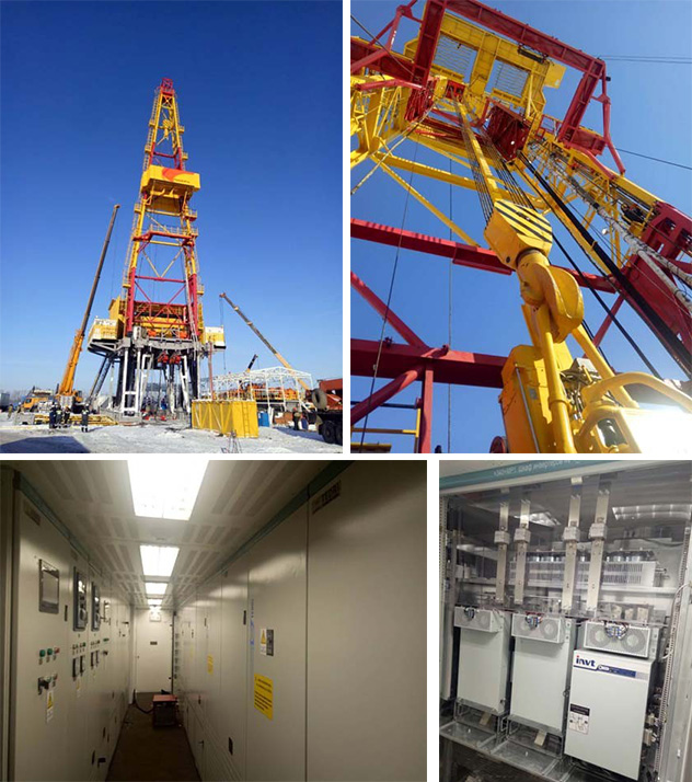
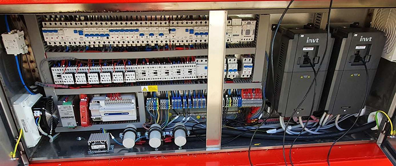
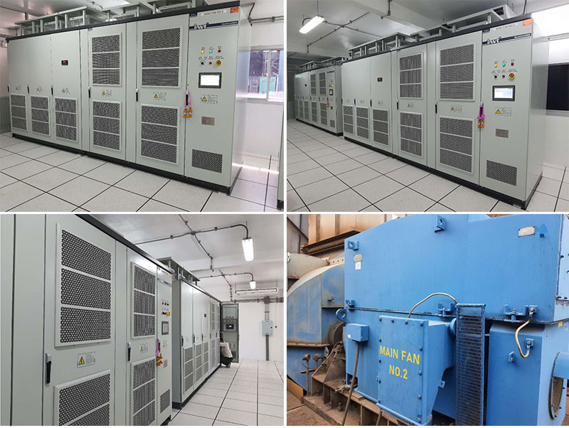
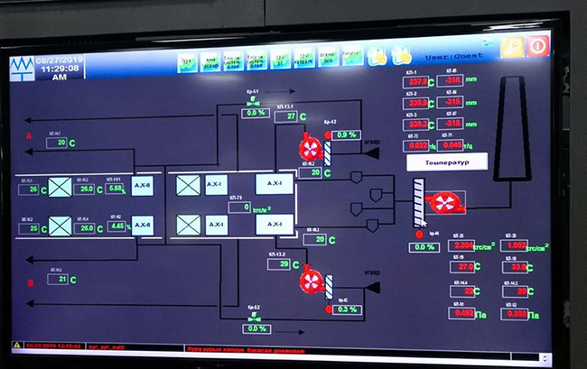
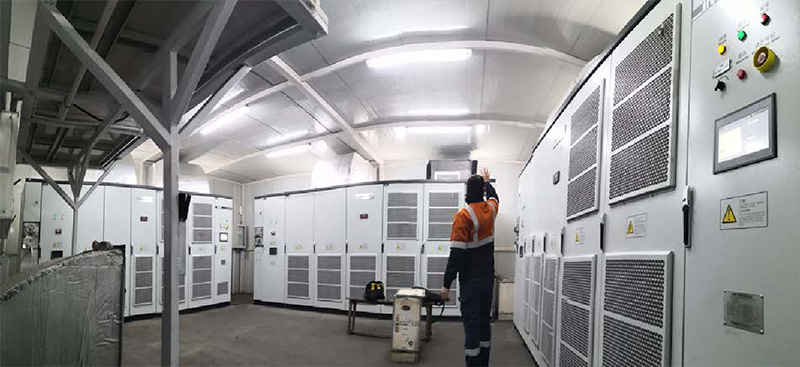
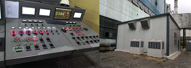
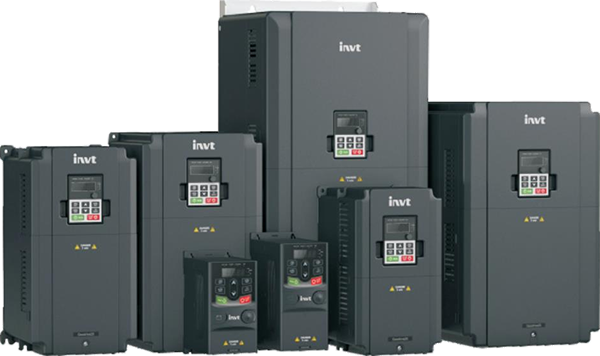
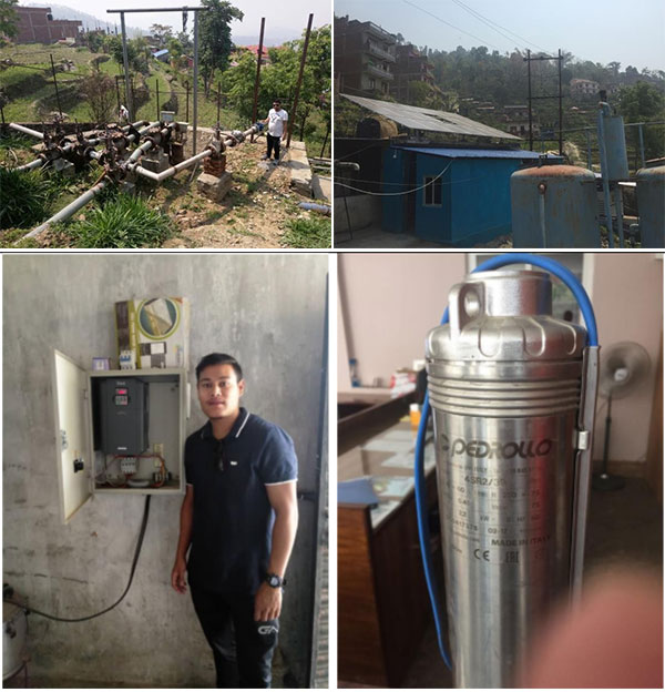
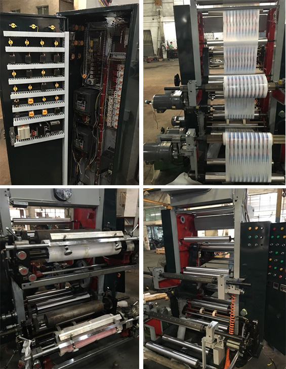
The panel and machine photos are as below:


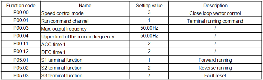
4.2 Parameters setting for inverters

Table 1: GD35-07 Winding inverter

Table 2: GD35-07 Unwinding inverter

Table 3: GD300 Drive (Master)


The inverter used for this system has the functions of short circuit, overload, over-voltage, phase loss, stall and other protection and fault output functions, which can effectively ensure the safe and efficient operation of the system.

5. Conclusion
The excellent characteristics of the inverter provide more excellent conditions for the printing quality of the printing press, such as over-current, over-voltage, overload and other aspects of protection, which can significantly improve the efficiency and performance of the printing press. The successful application of GD35-07 series tension control special inverter in several printing machine systems has provided the foundation for the promotion of our products and solutions in this industry.


Reference
[1] 《Goodrive 35 Series Close Loop Vector Control Inverter》Shenzhen INVT Electric Co., Ltd
[2] 《Goodrive 35-07 Inverter Special for Tension Control》Shenzhen INVT Electric Co., Ltd

2020年9月24日星期四

INVT GD5000 MV VFD is Applied in the Power Plant 3# of Mongolia

Abstract
According to the application of high voltage inverter in induced draft fan and forced draught blower, the energy-saving effect after the transformation is analyzed.

Keywords
Induced draft fan, forced draught blower, MV VFD inverter, energy saving, Ulaanbaatar

I.Overview

Induced draft fan and forced draught blower are the main equipment of the fan system of thermal power plant. They are one of the main auxiliary engines of thermal power plant, and their power consumption accounts for about 1.5-2.5 of the generating capacity of the power plant. The safety and economy of their operation is directly related to the safe and economic operation of generator set and even the whole power plant. Therefore, the reliability and economy of the blower operation has always been the issue of great concern to power generation enterprises, and controlling the volume of air intake and stabilizing the negative pressure value of the furnace are of great significance to ensure the boiler safety and economic operation.

Current medium voltage drive is widely applied to the field of power plant fan, MV VFD to introduce power plant Induced draft fan and forced draught blower for transformation will produce a lot of positive effect, it is able to run to a great extent, the fan in the process of realization of the goal of saving energy and reducing consumption and improve the system performance, can directly bring objective economic benefit for power plant.

II.Transformation situation

1.Operating Conditions
The third power plant of Mongolia is one of the three power plants (the power plant 2#, the power plant 3# and the power plant 4#) in Ulaanbaatar, ranking the second among the three power plants with a total installed capacity of 198MW, including 4*25MW generators, 4*12MW generators and 1*50MW generator. There are 13 high forced draught blowers and 2 induced draft fans. The previous way is direct power frequency start, because the power is not large, so there is no soft start device. As the power generation load is adjusted in a wide range, the wind volume of the fan needs to change with the change of the power generation load, and it often operates inefficiently in the power frequency state, resulting in a large amount of energy wasted on the wind duct baffle.

According to the change of unit load, the unit control system transmits the load instruction to the fuel system to realize the automatic balance of the whole system and achieve the purpose of safe and stable operation. Therefore, by adjusting the primary air pressure and air volume, the rapid load response of the fuel system is realized, and the high requirements are put forward for the supply and use of air volume. On the one hand, the system has strict requirements on wind pressure, which too much influences the flame shape of the burner and too low wind leads to insufficient combustion. On the other hand, the control of the system on the air volume is affected by many factors, the change of wind temperature, boiler load change, all directly affect the control index of the air volume. Since the air volume of the induced draft fan and forced draught blower cannot be adjusted at present and cannot well meet the needs of the boiler's combustion capacity and stable operation, the two forced draught blowers and one induced draft fan are reformed by frequency conversion according to the opinions of INVT to the customer. This can not only reduce energy consumption, but also effectively control the real-time variation of the air volume, and achieve performance regulation at the same time to save energy.

Refer to the following picture for the system process flow,


2.Primary power system strategy
In order to fully ensure the reliability of the system, The MV VFD is equipped with a bypass cabinet at the same time. When the MV VFD is fault, the MV VFD stops running and the motor can be directly manually switched to the power frequency run. The power frequency bypass consists of three MV isolation switches QS1, QS2 and QS3 (QF is the original MV switch of Party A). It is required that QS2 cannot be turn on with QS3 at the same time and interlock is realized mechanically. When MV VFD is running, QS1 and QS2 are turn on and QS3 is turn off. QS3 is turn on and QS1 and QS2 are turn off during power frequency operation. The worker can switch power frequency and frequency conversion according to the actual requirements of the site.

In order to realize the protection of the converter fault, the MV VFD interlocks the 6KV 'Users' switch'. Once the MV VFD fault occurs, the MV VFD will switch off the Users' switch, and party A is required to appropriately transform the closing and opening circuit of Users' switch. In the case of power frequency bypass, the frequency converter shall allow the Users' switch to turn on and cancel the trip signal to the Users' switch, so that the motor can start normally through the Users' switch to turn on the power frequency.

The design scheme is as follows


3.Control mode
Three MV VFD were placed in the same newly built room, about 60 meters away from the control room. We use the switch to realize two HMI to control the same MV VFD (one HMI in the MV VFD room and other one HMI in the control room), and use the network cable to realize high-speed communication. In this way, the customer can fully control the MV VFD in the control room, and can monitor and view all data of the MV VFD in real time, the most effective way to realize the control of the MV VFD.

The following is the communication diagram


III.VFD principle

INVT GD5000 series VFD is a high-tech energy-saving product, which adopts advanced IGBT power unit multi-level technology, digital control technology and SPWM pulse width modulation technology. It has the advantages of high power factor, high efficiency, energy saving, high stability, etc, and has the rated power energy feedback ability.

Each phase of the VFD is composed of six power units in series, and the three-phase Y is connected to the output. The output adopts the SPWM wave superimposed by six power units of each phase to form high-quality output waveform, which is supplied to the motor to drive the load.

Optical fiber communication is adopted between control cabinet, power unit cabinet, transformer cabinet and bypass cabinet to prevent electromagnetic interference. Achieve complete isolation of high and low voltage, improve safety.

The input side of the power unit is composed of fuse, rectifier and filter parts, and the rectifier part is composed of six diodes. The inverter consists of four IGBT H bridge inverter outputs, and the motor is driven by the unit series.

Power unit topology

Topology of VFD system


IV.Application advantages

1.Energy saving space is large
Before the transformation of the VFD, the induced draft fan is operated at a power frequency of 50HZ with no speed regulating device, the damper plate is adjusted to meet the demand of air volume. The actual operating voltage is 6kV, the current is 74A and the motor power factor is 0.78.

After the transformation of the VFD, the actual operating frequency is 44HZ and the actual input current is 52A.Baffle changed to maximum to reduce ventilation resistance. The power factor is 0.96 and the input voltage is 6kV.


Before the transformation of the VFD, the induced draft fan is operated at a power frequency of 50HZ with no speed regulating device, the damper plate is adjusted to meet the demand of air volume. The actual operating voltage is 6kV, the current is 39A and the motor power factor is 0.78. After the transformation of the VFD Drive, the actual operating frequency is 20HZ and the actual input current is 17A.Baffle changed to maximum to reduce ventilation resistance. The power factor is 0.96 and the input voltage is 6kV.


2.Reduce the current shock when the motor is started
When the motor starts directly, the maximum starting current is 7 times of the rated current. Motor soft starter is also 2.5 times. Double inspection of actual operation of the INVT MV VFD, it can be found that the start is basically no impact. The current from zero, only with the increase of speed and rise, basically will not exceed the rated current. Therefore, frequency conversion operation solves the problem of large current impact when the motor is started, eliminates the impact response force of large starting current on the motor, the transmission system and the host, and greatly reduces the daily maintenance cost.

3.Extend equipment life
The use of MV VFD can make the motor speed change along the acceleration and deceleration curve of the fan, without the effect of stress load on the bearing, prolong the life of the bearing. At the same time, the relevant data show that the mechanical life is proportional to the reciprocal of the speed, reducing the speed of the fan can double the life of the fan, the fan's use cost will naturally reduce.

4.Noise reduction
Fan after using MV VFD, reduce the speed of the fan running at the same time, the noise greatly reduced, when the speed reduced by 50%, the noise can be reduced by more than ten decibels. At the same time, it eliminates the skid and sharp contrast during shutdown and startup, and overcomes the defects of strong resonance caused by hammer strike and resonance of pipes due to poor linearity and poor quality of adjustment. After the fan frequency conversion operation, the noise and resonance are greatly reduced and the changes are considerable.

Photos of the converter in operation

V.Conclusion

After being used to adjust the blower and induced draft fan in the thermal power plant, the high voltage frequency converter can prolong the service life of the motor and blower, improve the production efficiency and remember the automation level, improve the reliability of the operation and power supply of the thermal power plant, save the energy and the cost of inspection, and bring great emergency benefit and social benefit to the thermal power plant. Especially the thermal power unit takes up the proportion of the total installed capacity is very high, the high-power auxiliary machines have traditional baffle valve control for inverter adjusting condition a lot, after transforming energy saving potential is very large, especially for coal-fired power plants in saving energy and reducing consumption, improve the economic benefit, improve the competitiveness of the feed-in tariff plays a huge role.


Reference
https://www.invt.com/solutions/mv-vfd-applied-in-power-plant-131

2020年9月10日星期四

Application of INVT GD100-PV inverter in Gurkha Nepal

Abstract: With the development of the photovoltaic industry, solar panels work more and more efficient. Meanwhile due to the exponential growth of photovoltaics, prices for PV systems have rapidly declined in recent years. So it is really a good timing to expand the photovoltaic market. GD100-PV, INVT product for photovoltaic water pump, has been kept upgrading to meet the requirements in the market. Benefited from the development of the electronic and internet, INVT has invested R & D resources for developing a new solution which makes installation simple and reliable. This article mainly introduces GD100-PV series solar pump inverter applied in a remote village in Gurkha Nepal.

Key words: GD100-PV, Photovoltaic, PV water pump, Nepal, INVT

1.Introduction

The deficit in electricity and high diesel costs affects the pumping requirements of community water supplies and irrigation; so using solar energy for water pumping is a promising alternative to conventional electricity and diesel based pumping systems. Solar water pumping is based on photovoltaic (PV) technology that converts solar energy into electrical energy to run a DC or AC motor based water pump.

There are many remote areas in Nepal where the solar energy is abundant. And for some places, the water resource is far away from where they live. So it is an efficient and economy way to use GD100-PV product to solve the problems that it is hard to get the water for living supply, irrigation and so on.

2.Background

It is a remote village in Gurkha Nepal that surrounds with mountains. The transportation there is not convenient and the steep mountain path is rugged and rough. Meanwhile, the resource of water is from mountain spring which is a bit far away from the village. So it is hard for people in village to get the water that is necessary to be used for living supply, feeding livestock, irrigation and so on, which disturbs local people a lot. The problem is solved successfully after using INVT GD100-PV inverter.


Some pictures about the local village

3.Advantages of GD100-PV series

GD100-PV Solar Drive

• Be suitable for single phase and 3-phase water pump.
• Built-in MPPT controller and excellent MPPT algorithm for various photovoltaic panels.
• IP54 cabinet solution, meets various harsh outdoor environments, and can be installed in the outdoor directly.
• Inverters lower than 2.2kW support the boost module.
• Support PV input and AC grid input together, realize the switching function automatically, without human intervention.
• Include water level control logic, avoid dry run status and added full water protection.
• Start smoothly for reducing the voltage spike to motor.
• Low start voltage and wide input voltage range give more possibilities for accepting multi PV strings configuration and different type of PV module.
• Digital intelligent control can Flexibly adjust and set pump's speed range. In addition to soft start function also can provide lightning protection, overvoltage, over current, overload protection function.
• Support GPRS module, people can operate the system by website platform or mobile phone apps.

4.Photovoltaic Systems

A photovoltaic system converts the sun's radiation into usable electricity. It consists of the solar array and the balance of system components. PV systems can be categorized by various aspects. The process contains both physical and chemical reactions in nature, as the first step involves the photoelectric effect from which a second electrochemical process takes place involving crystallized atoms being ionized in a series, generating an electric current.

Figure 1: Principle of photovoltaic


5.Two Solutions of GD100-PV

There are 2 solutions for different rated power segment pumps, for the pumps whose powers are lower than 2.2kW,the solution is as the figure 2, for the bigger rated power pumps, the solution is as the figure 3.

For low rated power pumps ≤2.2kW, when we configure the solar panels, the PV power is enough, but the PV output voltage is not enough, which requires extra quantity of solar panels to increase the PV voltage. To solve the problem, GD100-PV supplies the boost module, and supports low PV voltage input and high DC voltage output, which can reduce the quantity of PV panels.


Figure 2: Boost module + GD100-PV


Figure 3: Auto-switch module + GD100-PV

The auto-switch module which is optional can detect the PV output voltage, and send the signal to GD100-PV, inverter will control the contactor to turn on/off the AC input.


Figure 4: Water pumping system

6.Conclusion

Due to the GD100-PV product integrates so many features, such as reducing the PV input voltage, switching power input channel between DC and AC, high IP class IP54 and so on, the end users don't need to maintain the solar inverter any more after setting the parameters at the first time.

GD100-PV product can detect the PV voltage, and if it is less than the setting point, the driver will change the power input channel from PV to AC grid automatically. If there is only PV channel input, GD100-PV will hibernate in the weak sun light and wake up automatically in the morning.

7.Application in Gurkha Nepal

With the assistance of our salesmen and technical engineers, many people in village have installed GD100-PV inverters which really are greatly helpful for them. The local customer named Sunbridge bought two GD100-PV inverters of 18.5kW and 5.5Kw in a local government supporting project. Take 18.5Kw GD100-PV inverter for example, the configuration of solar panels are 72x310w=22320w. (72≈1.2x18500/310, '1.2' is experience value which can be adjusted in actual application). The related pictures are as below.


Some pictures of the drive and pump

Reference: https://www.invt.com/solutions/application-of-gd100-pv-inverter-in-gurkha-nepal-126

2018年10月9日星期二

Choose Green Transportation, Create a Clean Living Environment

The Origin of the World Car-free Day
At September 22 in 1998, some young people in France first proposed the slogan of “In Town, Without My Car”, and hoped that the city was flooded by cars can get a moment of peace and quiet. The citizens of 35 French cities voluntarily abandoned their private cars on this day. The day of 9.22 became the “city car-free day” in France, and it was also destined to be a far-reaching day. Later, France’s first car-free day was incorporated into the environmental policy framework by the European Union in February 2000. Since then, this event has rapidly expanded to the global level. Today, protecting the environment, promoting green travel, and developing energy-efficient and new energy vehicles have become global consensus.

On this day, many cities around the world will take measures and conduct events to  promote green travel and reduce dependence on cars. This special festival is a collective ritual after human beings enter the automobile society and embodying respect of nature and human, and reflecting on the transportation mode dominated by cars.


The Reasons for Low Carbon Travel
Since the car has become a daily transportation, people become increasingly dependent on self-driving travel, and urban planning and construction are also dominated by cars, which has intensified urban diseases such as traffic congestion and air pollution. Driving is originally for personal convenience, but it leads to inconvenience to everyone, increases social operating costs, and also encroaches on the road rights of pedestrians and cyclists, which is contrary to the people-oriented urban governance concept.

The Advantages of Low Carbon Travel
According to incomplete statistics: World car-free day for one day, the country can save 33 million liters of fuel.  World car-free day lasts for one day, reducing harmful gas emissions by about 3,000 tons. A small step for you may be, a big step for green and low carbon. The city, should be a city of people, not a city of cars. Driving a car less, maybe you will find a better life.

INVT Renewable Energy
As a leader in domestic renewable energy vehicle powertrain system, INVT continuously takes innovation as the source stimulation for development. INVT has developed motor controllers, driving motors and charging products which cover a variety of renewable energy vehicles such as passenger vehicles, logistics vehicles, sanitation vehicles and buses, forming a huge system of new energy power assembly into a green science and technology matrix. 

At present, the structure of INVT's renewable energy vehicle products is becoming more and more perfect. Taking the pure electric vehicle powertrain technology as the core, it has established a leading system platform and cored component research and development capabilities, and built a core competitiveness of product performance through advanced management capabilities and technical level. In the end, INVT has formed the competitive advantage in the renewable energy vehicle market.

INVT GD3000 Series Drive Applied to Oil Drilling Rig

Abstract: This paper has introduced the feature of oil drilling rig, INVT GD3000 series 3-level frequency drive, and the application ...